Research shelf / Electronics / Hybrid components
Written Updated
Circuit elements that are analogue and digital in the same device
Mixed-signal design converts between analogue and digital. These components do not convert: memristive drift, Josephson quantisation and phase-change switching are physically continuous and discrete at once, in the same element. The folder builds a simulation framework for them and then audits itself hard enough to publish a bug register.
Code exists and runs. Performance not independently checked.
Memristors, Josephson junctions, GMR and phase-change elements simulated across six phases — with a self-audit that found and published seven bugs in its own framework.
The component models are grounded in real device physics: the Strukov–Williams memristor with its R(w) and parabolic window f(w) = 1−(2w/D−1)², Josephson junctions at f = V/Φ₀ = 0.4836 GHz/µV with a Stewart–McCumber parameter βc = 0.076 (overdamped, no hysteresis), giant-magnetoresistance elements under a Stoner–Wohlfarth approximation, and phase-change memory as a thresholded two-state switch.
The framework runs six phases: foundation models, advanced models, a modified-nodal-analysis circuit solver, GPU acceleration, application engines, and an EDA export layer producing SPICE and Verilog-AMS. Verification is done by executing every code block and checking each physics claim against first-principles derivation and literature values — not by inspection.
The result is a document that mostly reports on itself. Seven bugs were found and registered, including a 10× error in the quantum-tunnelling-resistance alpha constant that made the modelled conductance unmeasurable, and a drift formula using Ron/D² where Strukov–Williams uses Ron/D — a factor of 10⁸ in absolute timescale, consistent throughout the framework and therefore invisible until someone checked it against the original.
Every number, and what stands behind it
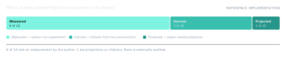
A claim is only worth the evidence attached to it. Each row below carries its basis: measured on the author’s own hardware, derived from the construction, measured on synthetic data, projected from literature, or simply cited.
| Claim | Figure | Basis | Context |
|---|---|---|---|
| Bugs found and published | 7 | Measured | Full register, all single-value or formula-level fixes |
| Josephson frequency constant | 0.4836 GHz/µV | Derived | Verified from 2eV/h = 483.6 MHz/µV |
| Stewart–McCumber parameter | β_c = 0.076 | Derived | Overdamped — no hysteresis, as modelled |
| Memristor R(w) / f(w) | verified at 5 boundary values | Measured | Python and SPICE export agree at every test point |
| Drift-formula discrepancy | 10⁸× vs Strukov–Williams | Measured | Code uses Ron/D²; original uses Ron/D |
| QTR alpha constant error | 10× | Measured | α = 10.25e9 → 1.025e9 m⁻¹ eV⁻⁰·⁵; fixes G₀ to 7.7e−5 S |
| Radau IIA step-count reduction | 21,032× vs backward Euler | Measured | ~7,000× net after 3× per-step cost |
| Adjoint gradient accuracy | 0.0002% vs numerical | Measured | dL/dR check |
| Shared-memory budget at n = 32 | 4.2 KB < 48 KB | Derived | Fits entirely on-chip per SM |
| GPU throughput figures | unverified | Projected | RTX 3090 numbers require hardware the audit did not have |
Measured — author-run experiment on the stated setup. Synthetic — measured, but on synthetic rather than real data. Derived — follows from the stated construction or proof. Projected — paper-stated projection, not an author-run benchmark. Cited — taken from external literature.
How it works
- Modified nodal analysis solver. The circuit-level backbone, verified independently of the component models.
- Warp-sorted GPU state machine. States sorted so each warp is homogeneous, eliminating the 4× SIMT divergence penalty; inverse permutation verified at zero error.
- Coalesced memory layout. (n,n,N) rather than (N,n,n) — one transaction per warp instead of a 64× penalty.
- EDA export layer. SPICE and Verilog-AMS emission, cross-checked against the Python models at every test point.
What it does not do
Taken from the folder’s own README. Nothing here has been softened.
- The memristor drift timescale is unphysical by a factor of 10⁸. It is self-consistent across the framework, so relative behaviour is fine and absolute timing is not.
- GPU throughput claims — 2.3 TOPS LU, 180 µs batched Euler, 48 ns real-time — could not be verified without the hardware. They remain document claims.
- IBIS export cannot represent hysteretic I–V at all; the standard assumes an LTI port. Valid only for single-state characterisation.
- Two of the seven bugs are in the Phase 4 application engines, which means those results need re-running.
- No physical devices were fabricated or measured. This is simulation throughout.
Free under AGPL-3.0+ for almost everyone
Personal use, charities, education and organisations under AUD 50,000 a year pay nothing. A tiered commercial licence covers everyone else.