Research shelf / Electronics / 100 W noise generator
Written Updated
A chaotic RF noise source where the Verilog is the specification
High-power wideband noise sources are a closed corner of RF instrumentation: the commercial units are proprietary, the chaos-circuit literature is scattered across analogue-circuits papers, and hobby builds top out around a watt. This folder’s move is to publish the digital supervision architecture for the whole stack as a single readable HDL file, and be explicit that the analogue performance is somebody else’s problem.
Specified in detail; implementation partial or absent.
One SystemVerilog file supervising a Chua-circuit analogue core, a four-band PA chain, supply DAC, thermal ADC and a sub-microsecond hard-protection state machine.
The noise itself comes from a Chua chaotic oscillator — an op-amp core with switched L/C/R banks and piecewise-linear nonlinearity segment selection driven by a chaos_dac injection. Around it sits a four-band RF power-amplifier chain (DC–500 MHz, 500 MHz–2 GHz, 2–6 GHz, 6–14 GHz), a 12-bit programmable supply DAC, and an eight-channel thermal ADC.
The protection subsystem is the part that justifies putting all of this in one supervised design: an 85 °C hard trip with a 77 °C warning, a 3:1 VSWR reference, an SCR crowbar, arc detection, and a fast-shutdown path budgeted at sub-microsecond, with a named fault taxonomy. A cycle-counted startup sequencer brings the rails up in order — auxiliary settle at 256 cycles, bias at 512, supply at 768, driver at 1,024.
The folder is unusually clear about what it is not. There is no research paper; the HDL header is the primary document. Phase noise, spurious-free dynamic range and flatness across the band are set by the analogue build, which lives entirely outside the file. The Verilog specifies control intent; realised performance is hardware-dependent, and the README says so before you ask.
Every number, and what stands behind it
A claim is only worth the evidence attached to it. Each row below carries its basis: measured on the author’s own hardware, derived from the construction, measured on synthetic data, projected from literature, or simply cited.
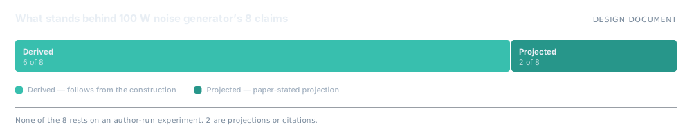
| Claim | Figure | Basis | Context |
|---|---|---|---|
| Banner frequency range | 1 Hz – 14 GHz | Projected | Header target; hardware-dependent |
| Banner output power | 100 W continuous | Projected | Header target; hardware-dependent |
| PA bands | 4 (DC–500 MHz … 6–14 GHz) | Derived | Band mapping from freq_pot |
| Thermal hard trip | 85 °C (77 °C warning) | Derived | MAX_TEMP in the protection state machine |
| VSWR trip reference | 3:1 | Derived | Protection subsystem |
| Fast-shutdown budget | sub-microsecond | Derived | Design budget in the state machine |
| Startup sequence | 256 / 512 / 768 / 1,024 cycles | Derived | Aux settle, bias, supply settle, driver settle |
| Supply DAC resolution | 12-bit | Derived | Programmable rail voltage |
Measured — author-run experiment on the stated setup. Synthetic — measured, but on synthetic rather than real data. Derived — follows from the stated construction or proof. Projected — paper-stated projection, not an author-run benchmark. Cited — taken from external literature.
How it works
- Chua chaotic oscillator. Switched L/C/R banks with piecewise-linear nonlinearity segment select — the analogue noise source.
- Band-mapped PA staging. Four amplifier bands selected from the frequency control, rather than one wideband chain.
- Hard-protection state machine. Thermal, VSWR and arc faults each with their own path to an SCR crowbar and fast shutdown.
- Cycle-counted startup sequencer. Deterministic rail-up ordering with explicit settle budgets.
What it does not do
Taken from the folder’s own README. Nothing here has been softened.
- No standalone research paper. The HDL header is the primary document and the README is the prose layer around it.
- The 1 Hz – 14 GHz and 100 W figures are header targets. Realised performance is set by an analogue build that does not exist.
- Phase noise, SFDR and band flatness — the numbers that actually characterise a noise source — are outside the file entirely.
- No synthesis results, no timing closure, no FPGA resource utilisation figures.
- A 100 W RF source is a hazard. Nothing here is a safety case.
Free under AGPL-3.0+ for almost everyone
Personal use, charities, education and organisations under AUD 50,000 a year pay nothing. A tiered commercial licence covers everyone else.